Tiếng Việt
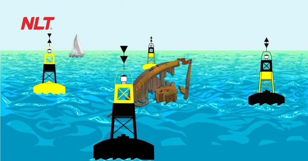
Alongside understanding how to select the right buoy, having a clear understanding of navigational buoy structure is equally important. Gaining insight into the structure of navigational buoys is not only essential for design engineers or construction contractors but also a critical requirement for management authorities and on site operators, ensuring that every buoy operates in accordance with standards, along the correct route and with the correct function. NLT Group provides a comprehensive overview of technical structures and the factors affecting proper installation of navigational buoys in compliance with current regulations.
What is an inland waterway buoy and its main functions
Definition according to QCVN 39:2011/BGTVT
According to QCVN 39:2011/BGTVT, the National Technical Regulation on Inland Waterway Signaling, a navigational buoy is a type of floating signal that is moored at a fixed position along a channel or within river, canal or estuary areas, serving the purpose of guiding, warning and channeling waterway traffic. Each buoy is designed with specific shapes, colors, signal light characteristics, physical structures and heights, enabling vessel operators to identify channel positions, hazardous areas or operational boundaries.
A buoy is not merely a simple floating object but a specialized signaling structure subject to strict management in terms of technical standards, positioning and operational regulations under the Ministry of Transport. Understanding navigational buoy structure enables more accurate selection and installation.
>> See more products: Inland waterway buoys by NLT here
Classification of buoys by function: channel marking, warning and mooring
Based on their primary functions, inland waterway navigational buoy systems are commonly divided into three main groups:
- Channel marking buoys: Installed at the left and right boundaries of navigation channels. Left side buoys are typically red, while right side buoys are green or blue. Signal lights use different flashing patterns to allow clear distinction at night.
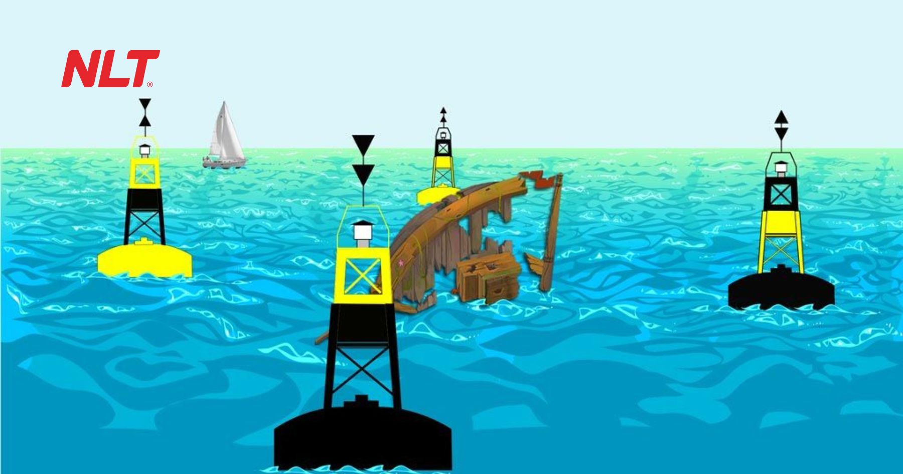
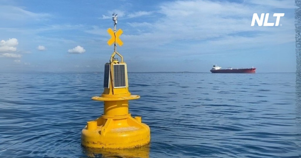
- Hazard warning buoys: Used to indicate submerged obstacles, shallow waters, reefs or construction works on rivers. These buoys are usually yellow, cylindrical or spherical in shape, with yellow flashing lights to attract attention.
- Mooring buoys: Installed in areas where vessels are permitted to anchor or transfer cargo. These buoys have specialized designs, higher load bearing capacity and typically do not use signal lights or only use single white flashing lights.
Each buoy type serves a distinct function and has a specific navigational buoy structure that cannot be substituted. Therefore, correctly identifying the buoy type prior to installation and operation is a mandatory requirement.
Why must navigational buoy structure vary by location and purpose?
Not all waterways share the same environmental conditions. Buoys installed in freshwater rivers have different material and structural requirements compared to buoys placed in marine environments. Buoys located in areas with strong currents, large waves or frequent impacts require more robust structures, using corrosion resistant materials such as thick HDPE plastic or galvanized steel. In contrast, buoys installed in canals, industrial zones or calm waters can adopt lighter designs that prioritize buoyancy and ease of installation.
Moreover, each functional type requires specific signal light designs, topmark shapes and paint colors, allowing vessel operators to quickly recognize them from a distance without confusion. As a result, navigational buoy structure depends not only on physical environmental conditions but also on the specific signaling function and warning role of each waterway.
Overall structure of inland waterway navigational buoys
Topmark and signal light – the primary identification components
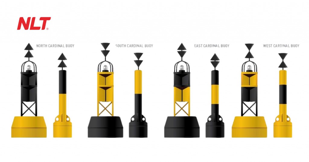
The first component in the structure of a navigational buoy is the Topmark, which is the directional marker mounted at the highest point of the buoy and used to identify the buoy type from a distance in accordance with the standardized signaling system. The shape and color of the topmark are regulated under QCVN 39:2011/BGTVT. Topmarks must be manufactured from lightweight, wind resistant, non corrosive materials with good retroreflective performance.
Example: cylindrical shape for left channel marking buoys, inverted cone for right channel marking buoys, and an “X” shape for obstruction warning buoys.
Directly below the topmark is the signal light (lantern), which provides illumination at night or under poor weather conditions. The light uses specialized LED technology capable of emitting flashing signals based on predefined codes such as single flash, double flash or specific flashing cycles. These signals help vessels identify buoy types and determine the correct navigation direction. The light is typically integrated with an automatic light sensor that turns it on at night and off when sufficient daylight is available. This is an indispensable part of the inland waterway buoy structure and plays a particularly important role.
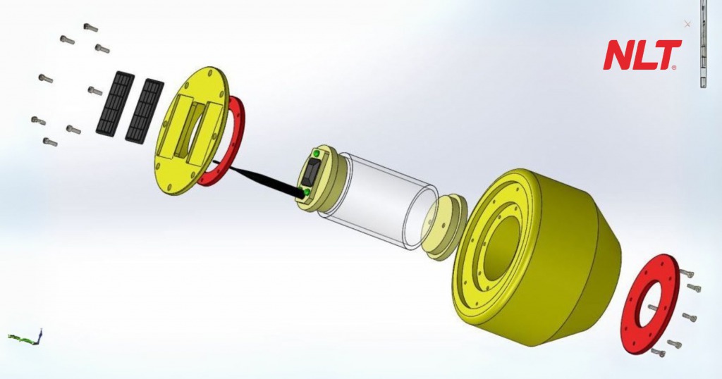
Solar panel, battery and technical compartment – electronic components
The signal light requires a stable power supply to operate continuously. As a result, modern navigational buoy structures are commonly equipped with solar panels installed on the side of the buoy or above the light. The solar panel charges during the day and stores electricity in the battery system housed inside the technical compartment.
The technical compartment, located around the mid body of the buoy, can be accessed via a stainless steel hatch, allowing inspection and maintenance of batteries, light controllers and internal electrical circuits. In some buoy types, this compartment also integrates GPS, LoRa or NB IoT modules to support remote positioning and monitoring.
All electronic devices must be installed within a sealed compartment that meets IP68 standards for water resistance, corrosion resistance, shock resistance and ease of replacement.
Floating body – materials, structure and buoyancy
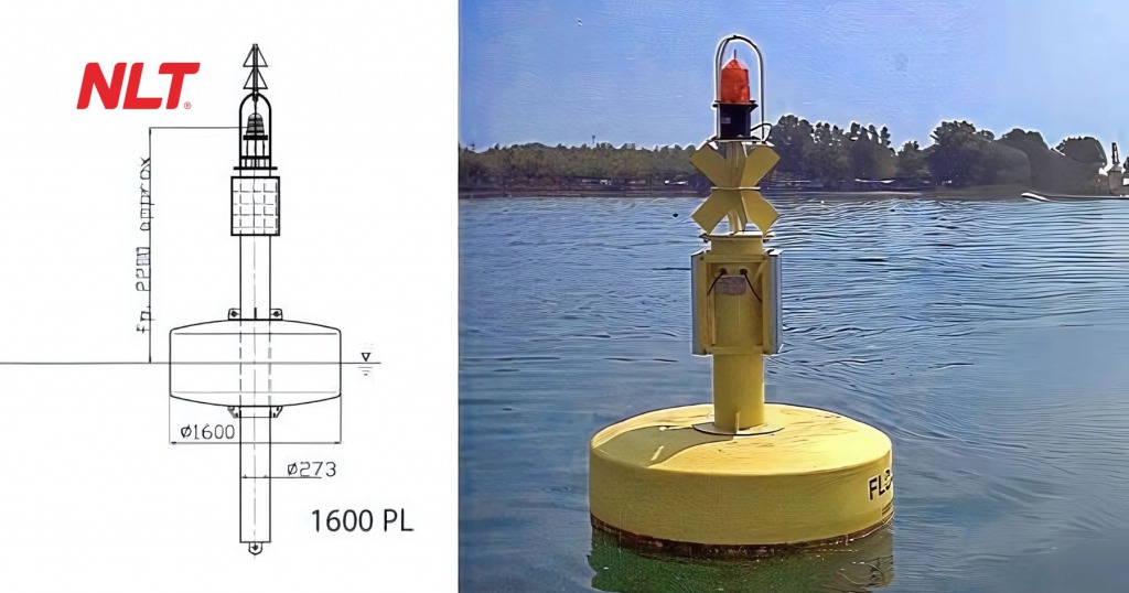
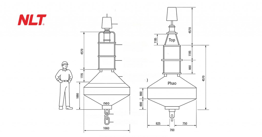
The floating body is the component that generates Archimedes buoyant force, allowing the buoy to remain afloat and stable on the water surface. According to the provided drawings, the floating body has the largest diameter ranging from 825 to 900 mm and is designed in a cylindrical or bulged round shape. This design increases the water contact area, helping reduce the risk of tilting in strong waves or upon impact.
Common materials include one piece molded HDPE plastic or fiberglass reinforced composite. The interior is filled with waterproof polyurethane foam to ensure the buoy remains afloat even if the outer shell is punctured.
The entire surface of the body is coated with reflective paint that meets color standards specified for each buoy function, such as red, green, yellow or black and white combinations.
Mooring hook, locking rings and conical base – stability and positioning components
Below the floating body is the base and mooring system, which is a critical component that keeps the buoy fixed in its designated channel position.
The base structure is designed as a truncated cone, helping reduce resistance from water flow and preventing the buoy from tilting when exposed to strong currents. At the lowest point is a stainless steel mooring hook, typically 32 mm or 36 mm in diameter, connected to submerged chains or mooring lines. This structure must ensure:
- No twisting of the mooring line when the buoy rotates 360 degrees
- No corrosion in saltwater environments
- Easy disassembly during maintenance
In addition, lifting bushes are provided to allow the buoy to be hoisted ashore or lowered into the water. These are usually securely welded to the internal metal frame within the buoy core.
Structure of smart navigational buoys with advanced features
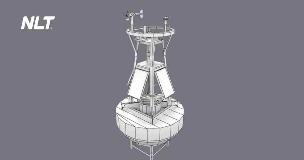
Special components in the structure of smart navigational buoys
Solar panels and energy storage batteries
Solar panels are typically mounted directly on top of the signal light or attached to the upper section of the buoy body in a sun facing orientation. Common power ratings range from 3W to 10W, sufficient to recharge internal batteries even under cloudy or foggy conditions.
The harvested energy is stored in lithium or sealed gel batteries with capacities ranging from 7Ah to 24Ah, depending on the buoy type. Batteries are usually housed in an IP68 waterproof technical enclosure and securely mounted inside the buoy body.
This system allows the signal light to operate continuously for 5 to 10 days without sunlight, ensuring nighttime navigational safety and complete independence from shore based power infrastructure.
GPS positioning and data transmission devices (LoRa, NB-IoT)
Smart navigational buoy structures are integrated with GPS modules to determine actual positions and compare them with design coordinates. This information is transmitted to the control center via wireless data networks such as:
- LoRa (Long Range): energy efficient, with transmission ranges up to 10–15 km, suitable for interconnected buoy clusters.
- NB-IoT: uses telecom infrastructure, providing stable signals within 3G/4G coverage areas, suitable for ports and urban environments.
This system enables control centers to monitor buoy status in real time, detect drifting, signal loss, light outages or technical faults without manual inspection.
Tilt sensors, light sensors and transceiver units
Some high end buoys are additionally equipped with:
- Tilt sensors: issue alerts if the buoy tilts beyond safe limits, typically 15–20°.
- Light sensors: monitor signal light operation and automatically report faults if the light turns off or flashes incorrectly.
- UHF/VHF transceivers: used in marine environments to transmit warning signals or synchronize status between buoys and shore stations.
These sensors play a critical role in early fault detection, reducing inspection manpower and advancing signaling systems toward automation.
Construction materials and technical requirements under QCVN
HDPE plastics, composite materials and galvanized steel
| Material | Advantages | Disadvantages |
| HDPE (high density polyethylene) | – UV resistant, does not become brittle or crack – Resistant to saltwater corrosion – Service life of 10–15 years | – Higher cost – Requires specialized molding tools |
| Fiberglass reinforced composite (FRP) | – Lightweight, easy to shape – Good water resistance – Can be reinforced per design requirement | – Susceptible to aging without UV protective coating – Brittle under strong impacts |
| Hot dip galvanized steel | – Rigid and strong – Suitable for mooring and frame components – Easy to fabricate | – Heavy – Prone to corrosion if galvanizing is damaged – Not suitable for floating components |
Requirements for UV resistance, saltwater resistance and corrosion protection
Due to long term outdoor operation under sun and rain exposure, navigational buoy structures must ensure:
- UV resistance: to prevent brittleness and color fading.
- Chemical corrosion resistance: especially in brackish and saltwater environments.
- Anti fouling properties: to prevent algae, barnacles and marine growth that affect visibility.
All buoy bodies and exposed components must meet minimum mechanical durability of at least five years without replacement, as recommended under QCVN 39:2011/BGTVT.
Water tightness standards and load bearing capacity
To withstand harsh operating environments, navigational buoy structures must meet the following requirements:
- Internal technical compartments housing batteries, controllers and GPS devices must meet at least IP67 standards, with IP68 being ideal, ensuring no water ingress during temporary submersion.
- The buoy body must withstand impacts from vessels approaching at speeds of 5–7 km/h without cracking, breaking or losing buoyant stability.
- The mooring system must withstand tensile forces of at least 3,000–5,000 N without twisting, breaking or causing the buoy to shift from its designed position.
Notes when installing or replacing navigational buoys
Do not arbitrarily change shape, color or light flashing frequency
Each buoy type has its own standardized identification in terms of geometry, color and light flashing patterns in accordance with QCVN 39:2011/BGTVT and the international IALA standards. Therefore, it is not permitted to change:
- Topmark shape: cylinder, cone, X shape, etc.
- Primary paint color: red, green, yellow, black, etc.
- Light flashing frequency and cycle: for example single flash 0.5s, double flash, etc.
Any non compliant modification may cause confusion in channel signaling, leading to collision risks and violations of inland waterway safety regulations.
Mandatory inspection and acceptance before commissioning
Before deploying a new buoy or after completing repairs, mandatory inspection and acceptance steps must be carried out:
- Measure buoyancy and balance level
- Check GPS coordinates against design data
- Check light intensity and flashing frequency
- Check water tightness of the technical compartment
All results must be recorded in the on site acceptance report, with signatures from the construction unit and the channel management representative, and archived in the technical documentation.
Update buoy data in the channel management system
After installation is completed, all buoy information must be updated in the channel management system, including buoy ID, GPS coordinates, technical condition, light type, commissioning date, actual photos and location diagrams.
If GIS software or remote monitoring systems are used, the above data will be automatically synchronized with the control center, enabling efficient management and rapid status checks at any time.
Conclusion
Navigational buoy structure is not only a matter of materials and engineering techniques, but also the foundation for ensuring warning signals function correctly, at the right location and at the right time. A small error in design or installation can lead to serious consequences for channel safety, vessel operations and legal responsibility. Understanding navigational buoy structure correctly, installing buoys properly and controlling operations accurately are the only ways to ensure that each buoy truly fulfills its role as the “silent gatekeeper” of inland waterway traffic routes.
FAQ
How many colors can be combined on a buoy?
Depending on its function, navigational buoy structure may include one or two combined colors such as red and black, yellow and black, or white and red. These colors must comply with QCVN 39:2011/BGTVT and must not be repainted arbitrarily.
How does a buoy light operate when there is no sunlight for many days?
According to navigational buoy structure using solar powered lighting, energy is stored in batteries, allowing the light to operate continuously for 5 to 10 days without sunlight, depending on battery capacity and solar panel efficiency.
Do smart buoys require periodic battery replacement?
Yes. Depending on the battery type such as lithium or gel, average service life ranges from 2 to 4 years. After this period, batteries must be inspected and replaced to ensure stable operation of the light and GPS system.
How does navigational buoy structure differ between river and sea environments?
Marine buoys usually have larger structures, wider bodies and higher resistance to waves and wind. Materials used for marine buoys must have better saltwater resistance, and the base structure and mooring hooks must be stronger than those of river buoys to withstand harsher environments.
Can custom buoy designs be ordered for specific routes?
Yes, but only within the limits permitted by QCVN. Any specific design adjustments such as dimensions, mooring structure or additional integrated devices must be reviewed and approved by competent authorities such as the Department of Transport or the Vietnam Inland Waterway Administration.